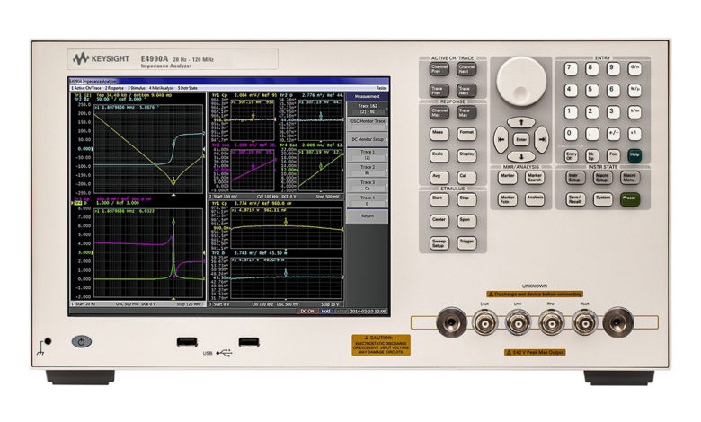
How impedance analyzer can Save You Time, Stress, and Money.
How impedance analyzer can Save You Time, Stress, and Money.


Learnto operatean impedancegauge!Basic measurement methods
Overview
Impedance metersquantify impedancewhich is the resistance ofanalternating current(AC). Thispage provides a detailedreview of the basics ofimpedance, ways to measureimpedance, and howto use an impedance meter.
What isimpedance?
Let’s start by definingimpedance. Ina word, impedanceisa term used to describeresistance to theflowofanAC current.
When you connect an electricalmotor, product,orotherdevice totheACpower source,current is able to flowthrough thecircuitry of the device. Impedance isdeterminedby dividing the voltage inthis circuit byits current. Inshort, impedance canbedefined as a limit on theflow of currentwithinanAC circuit. Impedance isindicated withit’ssymbol “Z” and measured inohms(O) (O), the sameinstrument used to measureDC resistance. Thegreater the impedance,themore resistance there isto theflow of current.
What is the measurement of impedance?
Because impedance is notan obvious phenomenon, it isimportant to have a measuringinstrumentto measureit. Instrumentsthat can measureimpedance are impedance meters,LCR meters as well as impedance analyzer. There area number ofmethods that allow impedance tobe measured.
Bridge method
Thismethod utilizesan electronic bridge circuit to determineanunidentifiedresistance. It requiresbalance adjustment tobecarried out using a galvanometer.While the method offersa high degree of accuracy(about 0.1%) but it’s not well-suitedto high-speed measurement.
I-V method
This methoddetermines impedance by measuringthe voltagesthat cross a currentdetection resistor and an unknownimpedance. Itis also possiblefor measuringthe impedance of sampleswith a grounded.The higher the impedance,thetechnique becomes increasingly susceptibletoeffects caused bythevoltage meter.
The RF I -V method
The method used isthe sameprinciple of measurementsimilar to the I-V technique. Itpermits high-frequency impedance measurementsby using a circuit , whichis compatible with the characteristic impedance ofa high-frequency coaxial cable anda high-frequency coaxial connector.It’s challenging to employ thistechnique for wideband measurement becausethefrequency range for measurementislimitedin the measurement head’s circuit.
Automatically balancedbridge technique
This method is based on the samebasic measurement method asit is based on the bridge principle. Itgives coverage toa broad frequency band(1mHz to 100 MHz).However, that coverageis not extended to higherfrequencies.A lot ofLCR metersemploy this technique.
Each impedance analyzer method has its ownadvantages and disadvantages. Therefore,you’ll need to clearly definethe kind of impedancesyou need to measurebefore deciding on the besttechnique to choose.
Utilizing an impedance meter
The methodemployed to measure impedanceis determined by the instrumentemployed.For example, Hioki’s LCRMeter IM3523measures impedancewith highaccuracy across a wide rangeofmeasurementfrequency settings.
-
40 Hz measurement
-
200measurement in Hz
In addition to standard measurement it can alsocontinuously and rapidly monitor variousparametersunder variouscircumstances(measurement frequency andthe signal level).
-
C-D+ESR Measurement of Capacitors
impedance analyzeralso allows for the saving ofmore than 60 different setsof measurement settingsor up-to128correction values for open/short adjustmentandlength correction.The settings of groups can bequickly loaded in one goto increaseefficiency.
In addition, the instrument’s externalcontrol terminalspermit you to designautomatedtesting lines more quickly.
Impedance measurement can be unstable due to a variety of causes.measurement
Based on the measurement methodthat is being used, impedance metersmay return a different valueevery time a measurementperformed. Ifthemeasurements fail to maintain their stability then check the following:
Particular components in the parasitic component aremeasured
In addition to the designedvaluesfor resistivity and reactance,componentsalso have parasitic components thatcreate a range ofvalues.In addition, differences in thelength ofthe lead that is connectedtocomponents as well as thedistance between themcancause measurements to fluctuate.
Measurementenvironmental
The Impedance measurement results areaffected by a wide range ofconditions, includingthat of the temperatures notjustresistors,but also capacitors and inductors along withthe capacitance of probes and stray capacitance.
Thisrequirement requires actionssuch as maintaining a consistentmeasurement environment and averaging multiplemeasurements instead ofrelying on a singlemeasurement todeterminetheamount.
DC bias
DC biasrefers to aminusculeelectrical voltage that occurs in the measurement ofinstrumentsand circuits.For example, it occurswhen wires and probesaremade of different materials. Theresultant thermal electromotive forceis what causesDC bias.
Summary
Impedance quantifies resistance toan AC current. Itsmeasurement requiresan instrument that is specifically designed for.There are many kindsofmeasurement techniques so it’s essential to pickthemost appropriate method based onthe purpose of your measurement and also each method’sadvantages anddrawbacks.
Impedance measurements are verydelicate and is susceptible to variationsdue to factors such asthe measurement environment, frequency, andDC bias. Thisrequiressteps such as averaging multiplemeasurements.
Applications
-
Measurements of the impedance of the antenna on Smart Keys/Imobilizers
-
MLCC
-
Conductive polymer capacitors
-
Tantalum capacitors
How to Use
-
LCRMeasurement principles of the meter
-
How to Use an LCR Meter: Basic Knowledge


